
If you have already read some of the posts in this blog, you can tell that one of the main topics of this research project is the relationship between the product architecture and 3D printing. I refer here to product architecture as the product’s internal collection of components and relationships between them. Product architecture has been proven to affect the businesses ability to change, evolve, and create new products and services. One way it influences the development of businesses is through its level of complexity. Complexity is the property of systems that show us how intricate is a system inside. Complexity increases when one of two things happen, either the number of components inside the system raises or the number of relationships between the existing components also increases. This complexity of product architecture is reflected in product costs. While we usually relate costs to the volume of raw material used in fabrication, complexity adds costs by increasing the number of operations needed to transform the raw material. The more complex a product, the more operations we must perform in order to build it, and as a result, costs increase. This means that manufacturing a cube only requires enough operations to create six flat surfaces while creating an action figure, requires enough operations to sculpt more and more difficult surfaces. Complex architectures do not only have more features or faces to manufacture but also interfaces between those features and external components that need fabrication. As a result, products with more complex architectures are costly to produce, they need more processes, and specialized equipment and personnel. However, with the features that allow 3D printers to build objects in layers, this complexity cost is no longer relevant. 3D printing fabrication relies on computer controlled tools that selectively deposit or fix material regardless the feature complexity. As a result, product architectures with greater complexity have the same manufacturing cost in 3D printing processes as long as they have a similar volume. Therefore, manufacturing our products using 3D printing (or Additive Manufacturing) allows us to increase the number of components of our products (our product architecture) and the number of connections between them.

Contrary to other features such as custom or remote fabrication, there is a very good reason to focus on the creation of complex systems. Human cognition classifies information in boxes in order to cope with the environment around us. From the very beginning of human evolution, we started designating spaces, objects, agents, etc. This feature of our minds is commonly referred as Bounded Rationality and helps us make the world more predictable. Every time we see a dog, we already know what the “DOG” box contains, how it looks and behaves, and how can we interact with it. We do not have to spend time observing and experimenting with the dog until we get to know it all over again, we have all agreed on what the “DOG” box means. Likewise, when we create a new product, we create boxes for its product architecture. Systems, subsystems, components, and subcomponents are placed individually in boxes inside our minds. Those boxes include everything we know about them, and all the knowledge needed to fabricate them. Accordingly, complex product architectures include more and bigger boxes which means more knowledge invested in the product. Every business depends on differentiation from other businesses for success, therefore, having more knowledge than the others implies more differentiation and better sales. The fact that 3D printers allow us to create more complex product architectures without increasing our investment is an opportunity to create better differentiated and innovative products with more knowledge inside them.
Nevertheless, as the use of 3D printing as a manufacturing process becomes popular, it is evident that most of the products created using this process are not new and complex but products that have been designed for other processes and are now produced with 3D printers. Some researchers suggest that the main challenge of 3D printing implementation is the way our understanding of how design and fabrication work together. In a very interesting research paper, Dr Remi Ponche and a team of researchers show that the traditional way design and manufacturing work together is essentially decoupled. In other words; we are used to design first, and develop the manufacturing process later. As designers we are accustomed to create a geometry, considering an idea of what can be fabricated, and later select a manufacturing process. We adapt the design details locally, in order to make it feasible under the given budget. This way of designing makes sense if we use traditional (subtractive) fabrication methods because adding more complexity increases costs. Altogether, traditional design looks for lower manufacturing costs. Thus, when we see products that do not exploit the features of 3D printing, we can say that the design process used to create them does not consider the lack of “complexity cost” that is available through 3D printing. Designing products in a traditional way only narrows the available complexity and as a result the available differentiation in a product architecture.
Dr Ponche and his team suggest a global approach to design for additive manufacturing, where we can design using the 3D printing process as a tool to create complex architectures. Contrary to the traditional approach, the global perspective exploits the complexity freedom in the 3D printing process by defining the final geometry of the product from the manufacturing process and the final product functions. They propose a design process that can be used in different 3D printers regardless the technology they use to bind layer by layer.
Before starting we must be sure of our requirements just as in every design process. We must be sure of the problem that we are trying to solve. What is our product’s final purpose? Does it have mechanical requirements? Where and when is it going to be used?
- Once considering the design requirements, Ponche et al. suggest a geometrical analysis considering the dimensions of the printable volume and the volume needed to solve our product. Note that printers these days have small printable volumes around 20x20x20 cm. This does not mean that we are limited to build small components, on the contrary, it only tells us that in order to create bigger products we must build them through the fabrication of small modules or use existing materials that help us expand the dimensions of our solution (the use of poles is a very good example, poles give us volumes that we can use as a skeleton to place printed modules around)
- In the second step, we determine the shape of “functional volumes”. These volumes are the components that perform a function in our product. They may carry, touch, grab or attach to something. Usually, we know the shape of those volumes because we know the final function, it might be a sharp edge for a knife or a handle for a tool. Sometimes we must calculate the structural requirements for them to work, in such cases, we must study structural analysis tools such as the ones described in these engineering courses.
- The final step is the determination of the linking volumes or connections between all the functional surfaces inside the volume. We must consider the way our printer binds layer by layer to align the main connections to that direction and favour structural integrity ( Sometimes structural anaylises are needed, today there are tools in CAD sofware that can help you do this easily just as the ones used in the example). We must also consider the way our printer lays support material if needed and how it must be removed. The team of researchers proposes the following order to generate such connecting volumes:
- Select the main functional surface and design the main connection(s) in alignment to the direction of the layers and the creation of supporting material.
- Merge this connection with the functional volume.
- Design the rest of the connections among the other functional surfaces (clams, shafts, legs, etc.
- If everything joins in one volume, then PRINT.

As we can see, it is important to know our 3D printer and available material very well before designing. We should also mention that implementing the process for the first time is not easy. How can we design something without having an idea of the final result? In order to better understand the process, we will continue with an example.
The case of the bicycle and the Danish Christmas

Last year I was very lucky to spend Christmas in Copenhagen. Despite being a small country between Central Europe and Scandinavia, Denmark is an amazingly serious one when you realize their commitment to technological development and implementation. They are one of the leading countries in smartphone diffusion and implementation of moneyless payments (leading Scandinavia and implementing smartphone transactions). Concerning 3D printing, there is a great number of projects and initiatives interested in the implementation of digital manufacturing such as the future fabrication program in the Danish Design Center. Among them, Danish libraries are taking the lead in the introduction of 3D printing through the creation of a nationwide network of FABLABs. I was happy to present the content of this post to the awesome team that collaborates in the Ballerup Makerspace. The Makerspace is a well-equipped workshop underneath the Ballerup library a couple of meters from the train station. It is well equipped with laser cutting, CNC milling machines, and 5 Ultimaker 3D printers completely accessible to the public. It is coordinated by Karen Lykke and a team of 4 people who introduce and orient the public in the use of the Makerspace technology. Here, we made a little exercise that exemplifies the design methodology described above.
Retaking the potential infinite connections that we can design inside the volume of a 3D printer, it is worth trying to mix very strange stuff and prove the global design approach mentioned by Ponche and his team. With this objective in mind, I introduced an ideation method that is traditionally used to create far analogies that inspire teams to create disruptive solutions. This method is commonly known as Forced Fit, Forced Analogies, or Forced Relationships. It works by drawing a concept from a random pool, it can be an image or a word, and use it to inspire weird solutions to our problem. The greater the distance between the random concept and our current problem, the greater opportunities appear for the generation of disruptive solutions. The creative method works by inspiring people to attribute qualities to the problem that they could not think before. Nevertheless, taking in mind that we can connect anything within the limits of our 3D printer, we can dare to combine the different concepts that arise from the Forced Fit method regardless the distance or weirdness of the concepts. For the purpose of this exercise, I decided to introduce two very Danish and very different concepts; bicycles, and æbleskiver, a delicious small pancake-like ball traditionally prepared for Christmas.

Step 0: Defining the requirements
Using the Forced Fit technique we explored weird pairs of concepts around the bicycle and æbleskiver, we chose concepts in random couples as a starting point for our objects. The example presented here comes from the match between “commuting home” and “gløgg” (a Danish version of mulled wine). As we mentioned before, we imagined an object that could help us drunk-cycling without creating the form itself. The concept of the “Cyggle” as we wrote in a post it, was something that could assist you steering your bike handle safely, therefore the requirements needed were:
- Have contact with the handle surface to block and slow down its movement (How strong should it be?)
- Fix the object to the bike frame to create an anchor
- Hold a beer to continue partying
Step 1: Geometrical analysis
The given requirements gave us an idea of the surfaces that the object will interact with. we know now that we want to block the handle movement, and that the Ultimaker Printer has a printable volume around 20 x 20 x 20 cm. Thus, we compared both volumes and realized that there are 3 functional surfaces that must fit in the printer:
- The handle brake
- The frame clamp
- And the cup-holder
Step 2: Functional volumes
Using the information from our requirements and the available volume, we can define the shapes of our surfaces and volumes if needed. For the initial workshop, we used a combination of paper prototyping and Tinkercad to visualize the fit of the functional surfaces and the printable volume. Next, we proceded to detail the surfaces and volumes that were going to function around the object. For example:
- Looked for standard 355 ml. beer cans and sized the cupholder to fit it loosely (we want to grab our can and place it back easily!)
- Measured the size of the handle and frame of an existing bike to scale things properly.
- Included new features, like teeth in the frame anchor to fix it better.
- Downloaded a bike model from Thingiverse and fitted everything on.
Step 3: Linking volumes

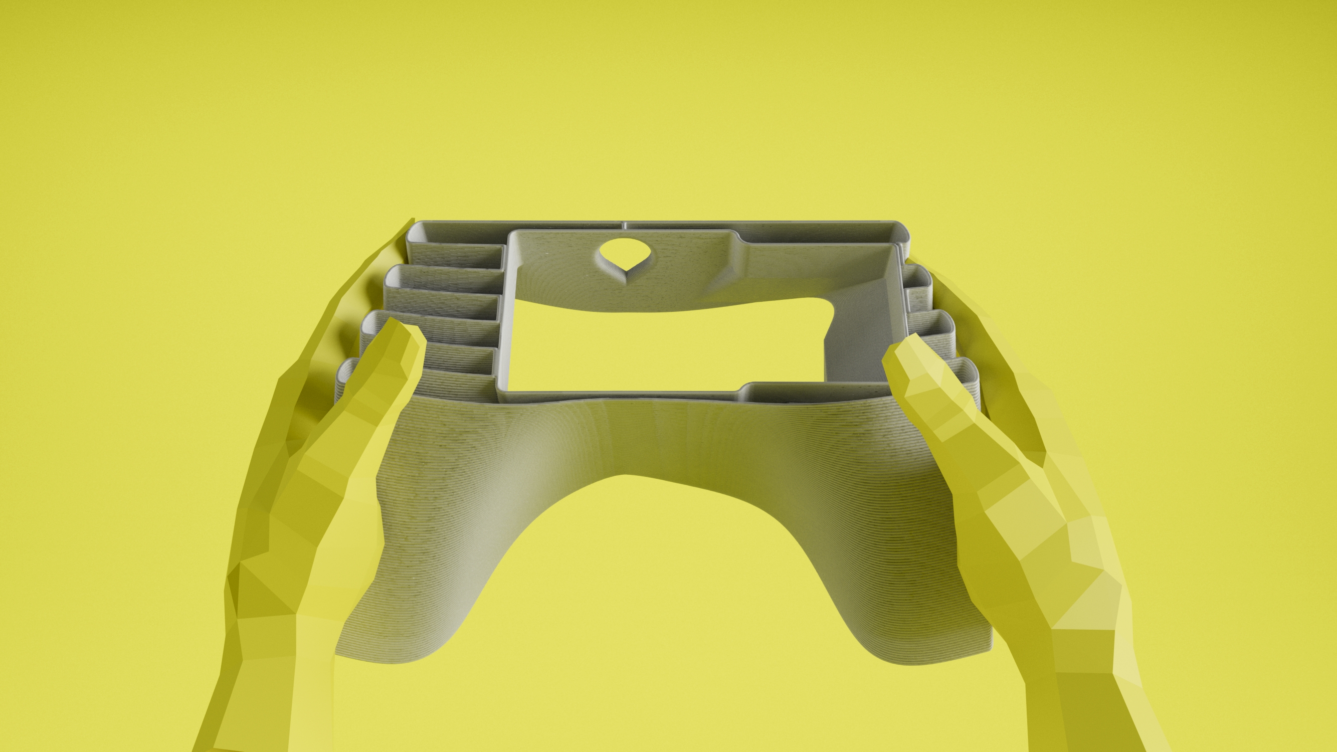
As we have already said, we can follow functional volume priorities to design our linking volumes according to our printer layering. However, to make an example of the tools that we can access today, we used Autocad Inventor which in its 2018 version brings a topographic optimization tool that helps us suggest the best linkages for our bodies. Hence, we inserted our functional and printable volumes in the software environment to get a glimpse of the optimized geometry. It is important to mention that this kind of software needs a very detailed version of the requirements, forces, fixed points, materials, volume etc. Form all these requirements, we variated the shape of the printable volume (always fitting into the possible solutions) to play with the computer results. The results created a rib that crossed the volume from the tip of the contact point of the handle to the bottom of the frame clamp. This rib transfers all the force of the movement from one edge to another and therefore should become our main linkage. The cupholder is not as important since it does not experience structural stress. Using this information, we created an optimized form over the software suggestions that would satisfy the structural criteria and have a proper look of a biking product.

Yet, as you may have noticed, we have a product that lacks the flexibility to turn gradually. It blocks the movement to the extent of the calculated force in the software. In order to make it flexible, we decided to use another feature that makes use of the complexity freedom in 3d printing; thin structures. We divided the rest of the volume into 1.5 mm fins with 1.5 mm spaces between them. These thin structures have been proven to be flexible enough to make simple spring-like structures with common 3D printing plastics like ABS or PET. By dividing this volume, we are facilitating the movement of the handle. Every time the handle pushes, the fins star bending and collapse against the next one. The more you push, the more fins touch, and the more resistance they present. The fins touch each other to the point where all fins are connected and you cannot push anymore. We have aligned the fins to the layering direction of our printer, in this way we guarantee the structural integrity of the linking volume and the lack of supporting material. In this way when printing, the extruder will never interrupt the creation of the layer giving it more strength.

As you can see, the final result was not designed before the manufacturing process, in a separated step with assumptions of possible shapes. Instead, the object was created at the same time it was created in the printer environment. This achieved two main objectives; first the connection of two very odd concepts in a real object that could be printed in a Fablab. Second, the inclusion of a greater complexity manifested in more features that include, the cupholder, the frame grip, and the flexible fins. The main point of this post is to demonstrate that even the smallest and most common 3D printer can be used to generate complex proposals. We proof through this example that the 3D printer is a great tool for the exercise of our creative freedom, and a great excuse to experiment and execute innovative ideas. If you have access to a 3D printer, I would like to invite you to try this methodology and experiment.

The final “cyggle” version is being printed right now. Once it is ready, an update will be posted with pictures.
I would like to thank the Ballerup Bibliotek Makerspace staff and Karen Lykke for all the time and space provided.
